MAME
Building the cabinet
This page contains the build process of my MAME cabinet. My main reference was Project MAME build at koenigs.dk. The majority of this build was based on his process and plans. I modified the plans slightly to better work with my monitor and control panel.
I built the cabinet out of 3/4" MDF, of which I required two 4' x 8' sheets. I had to have Home Depot cut both sheets lengthwise in order to fit them in my car. I got home with four 2' x 8' half sheets.
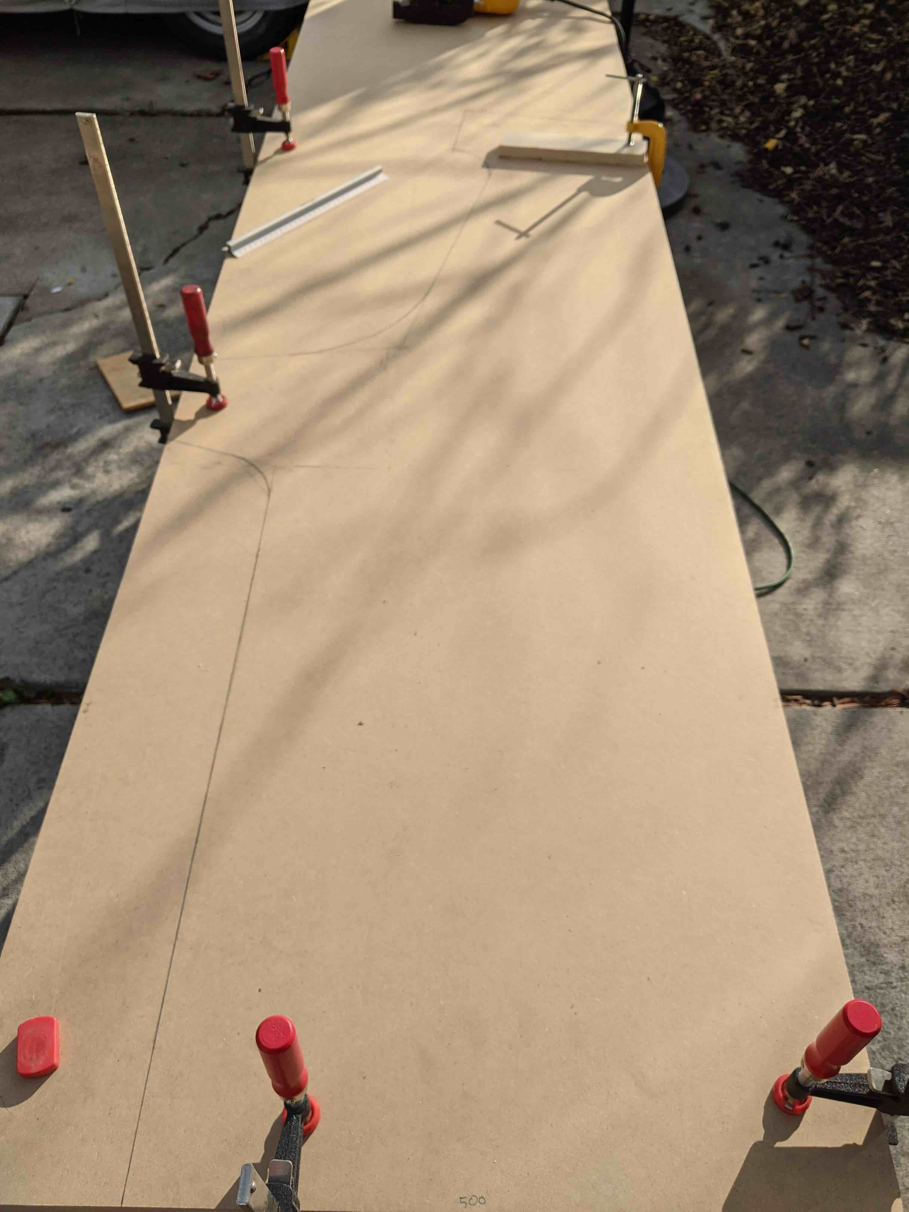
Using the plans from koenigs.dk as a starting point, I first sketched out the side panel on one the 2' x 8' sheets.
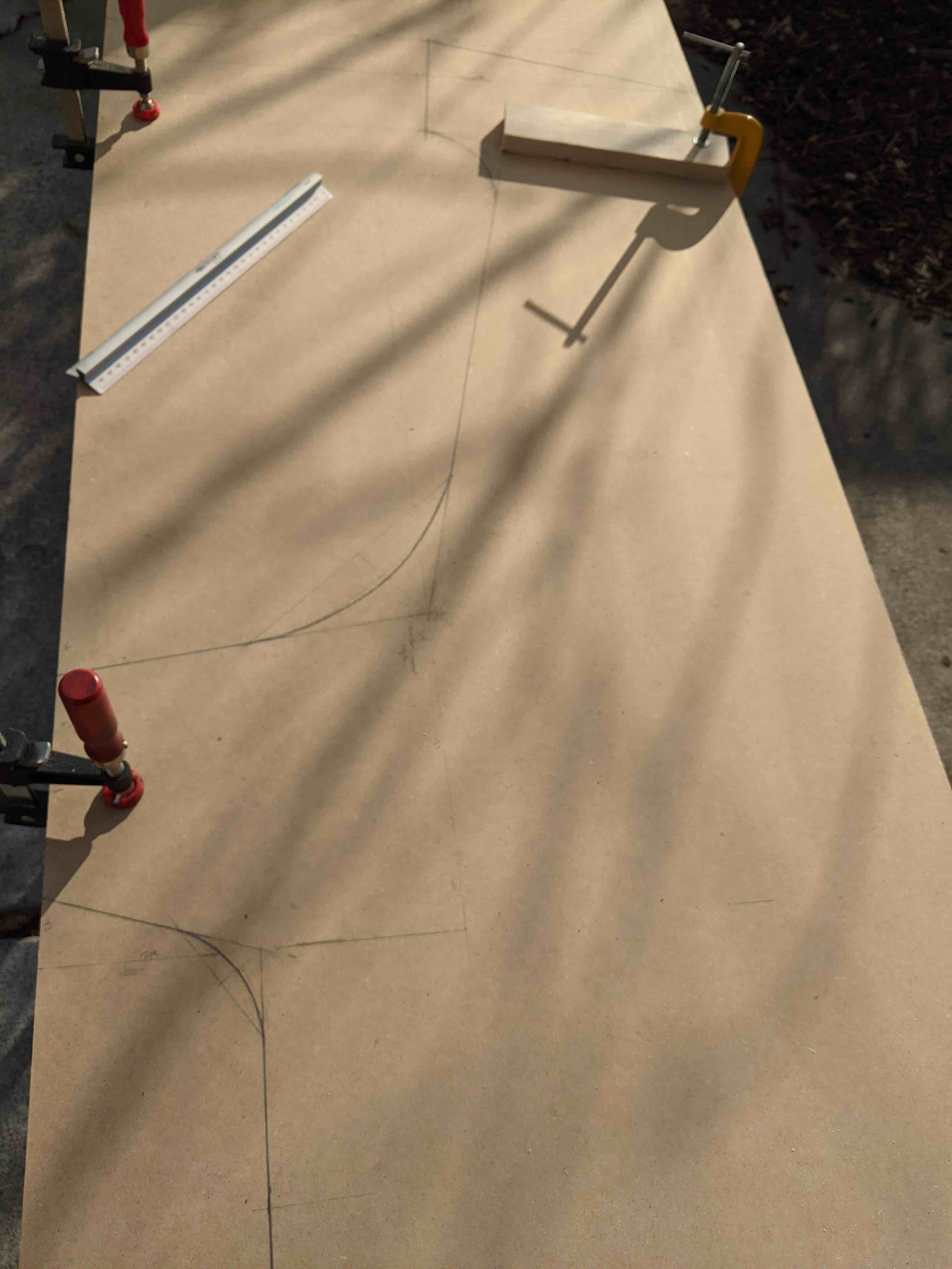
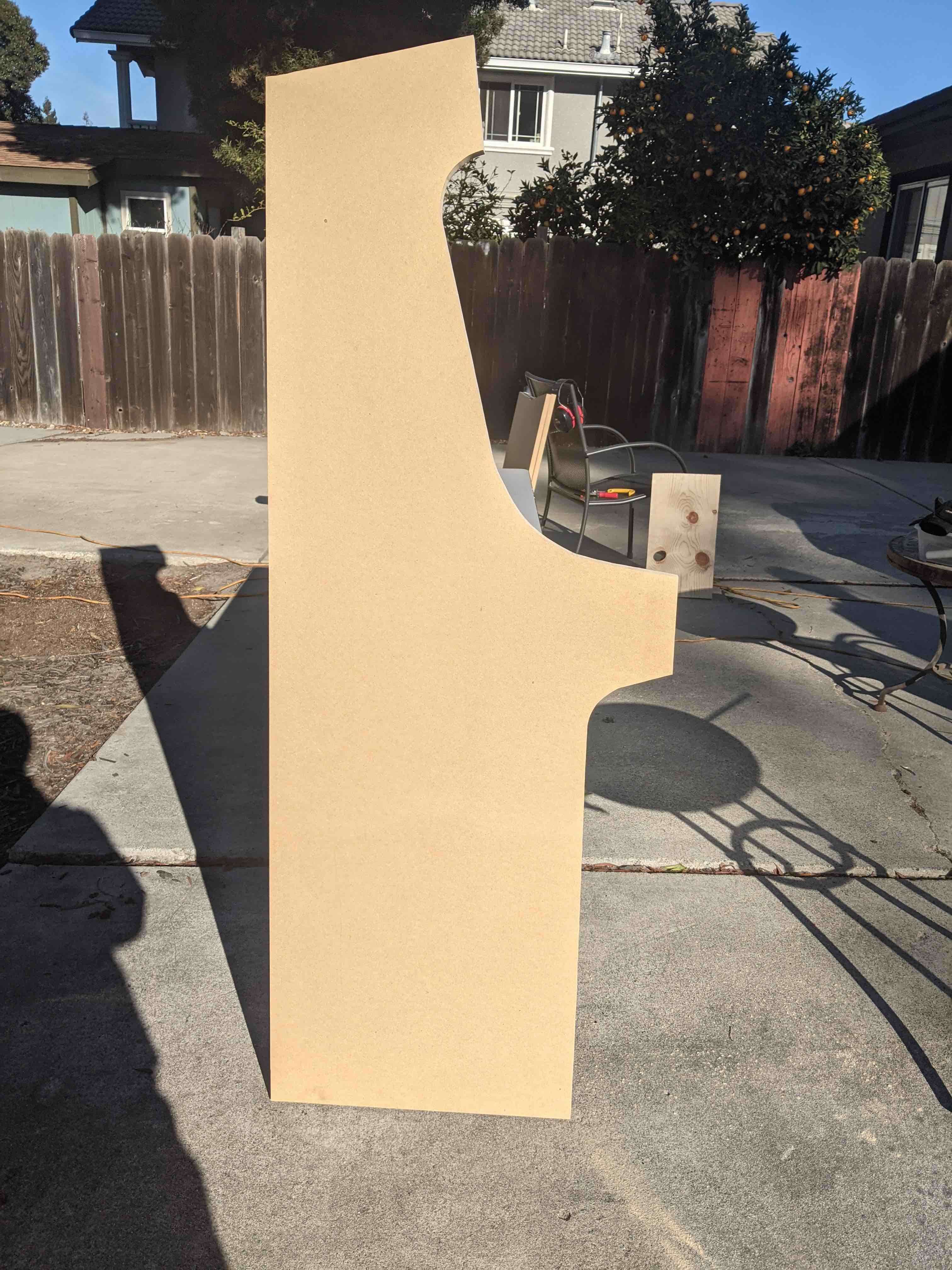
Once satisfied, I clamped on a second sheet and took a jigsaw to them to get both of my side panels.
Once again using the koenigs build as starting point, I sketched how the interior panels would sit onto one of the side panels. These would be the panels that stretch in between the two side panels. There were a few unknowns at this point that mostly revolved around the fact that I had not yet decided how I wanted to mount the monitor and the exact layout of the control panel.
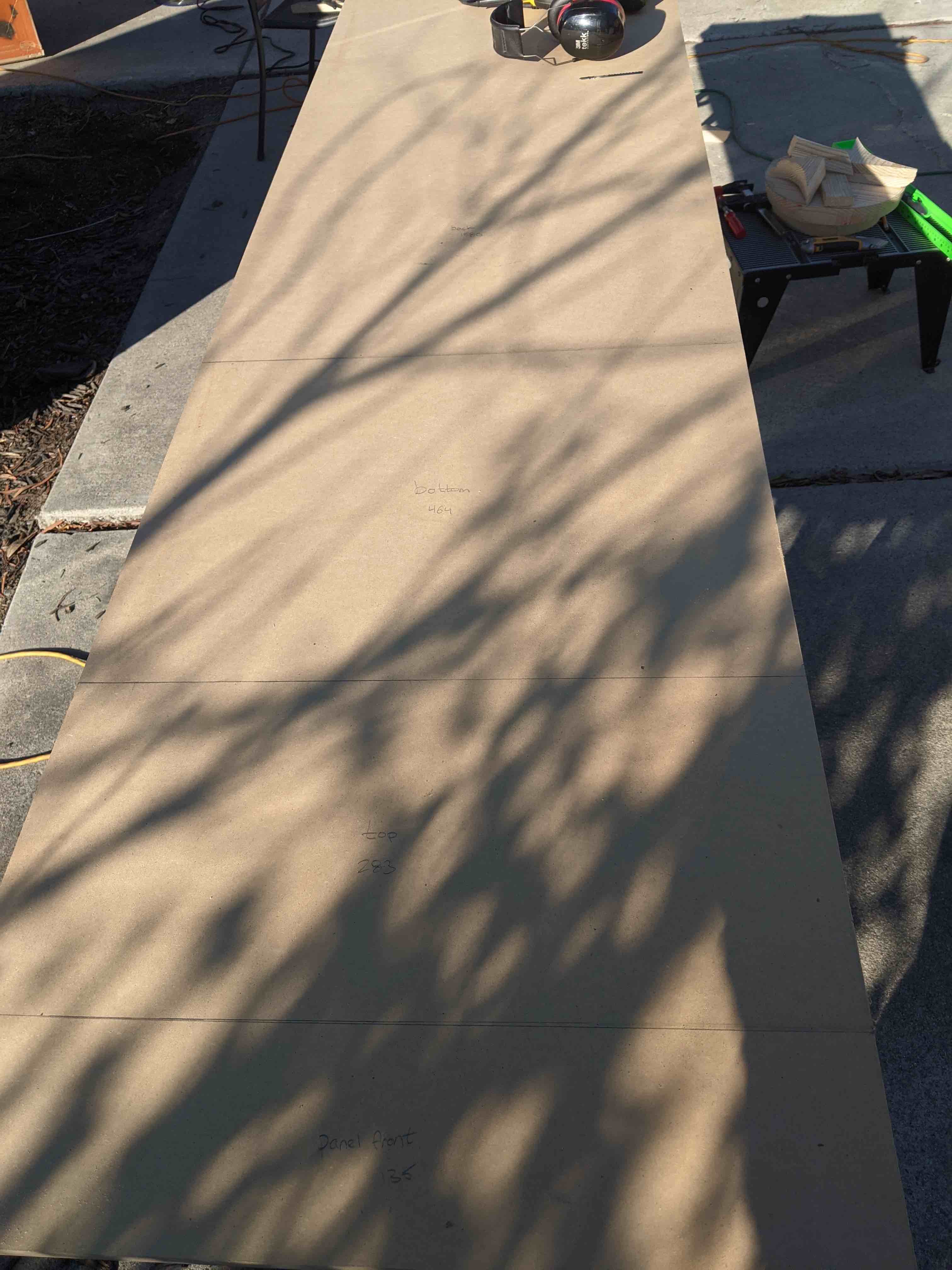
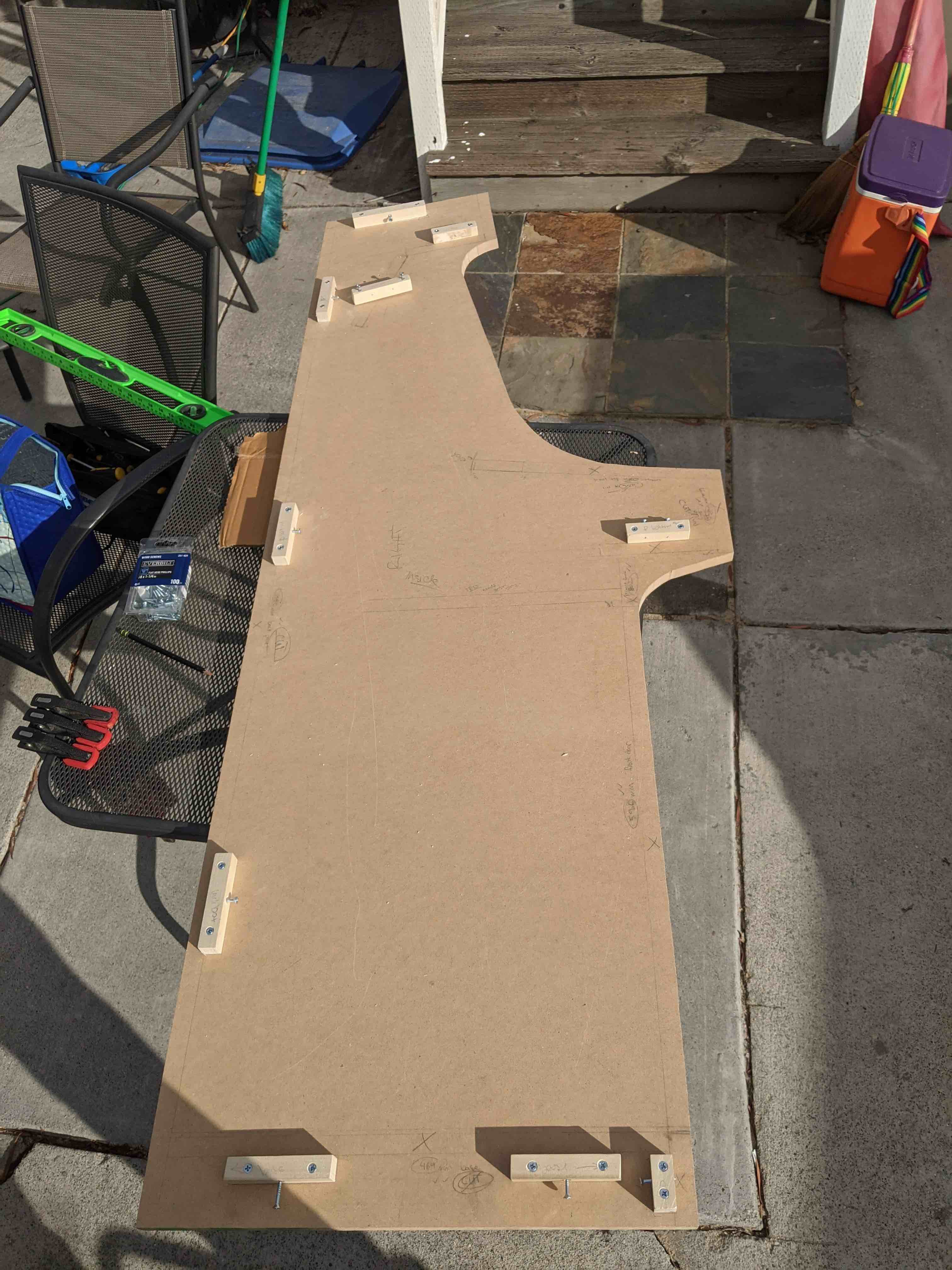
I measured out the lengths of the required panels that would sit in between the two side panels. This used the majority of the remaining two MDF half sheets. For the control panel, I measured out a piece a bit larger than I knew I would need, since I could always trim it down afterwards. I had about 2' remaining which would be more than enough for mounting the monitor. The photo below shows some of these measured out panels somewhere behind the shadows. Once measured out, these were quick cuts with a table saw.
With the interior panels cut, I moved on to adding the moulding to the side panels in order to attach the interior panels. Starting with the outlines of the interior panels and some 3/4" x 3/4" strips, I set up the moulding to hold the interior panels in. At this point, I did not yet add glue, since I wanted to first do a dry fit so I could work through the control panel and monitor placement.
From here, I dry assembled the cabinet to double check the fit and it all fit pretty well! At this point, I left out the control panel, drawer, and front door. With it put together, I could start messing around with the exact placement of the speakers and monitor, as well as get measurements for the plastic for the bezel, screen, and control panel top.
Once I got the plastic for the control panel top, I could start getting the control panel set up. I already had an X-Arcade Tankstick which I wanted to gut and remount the hardware directly onto the cabinet. I copied over the layout from the Tankstick onto a fresh piece of MDF that I would cut with the plastic to make sure it's all aligned.
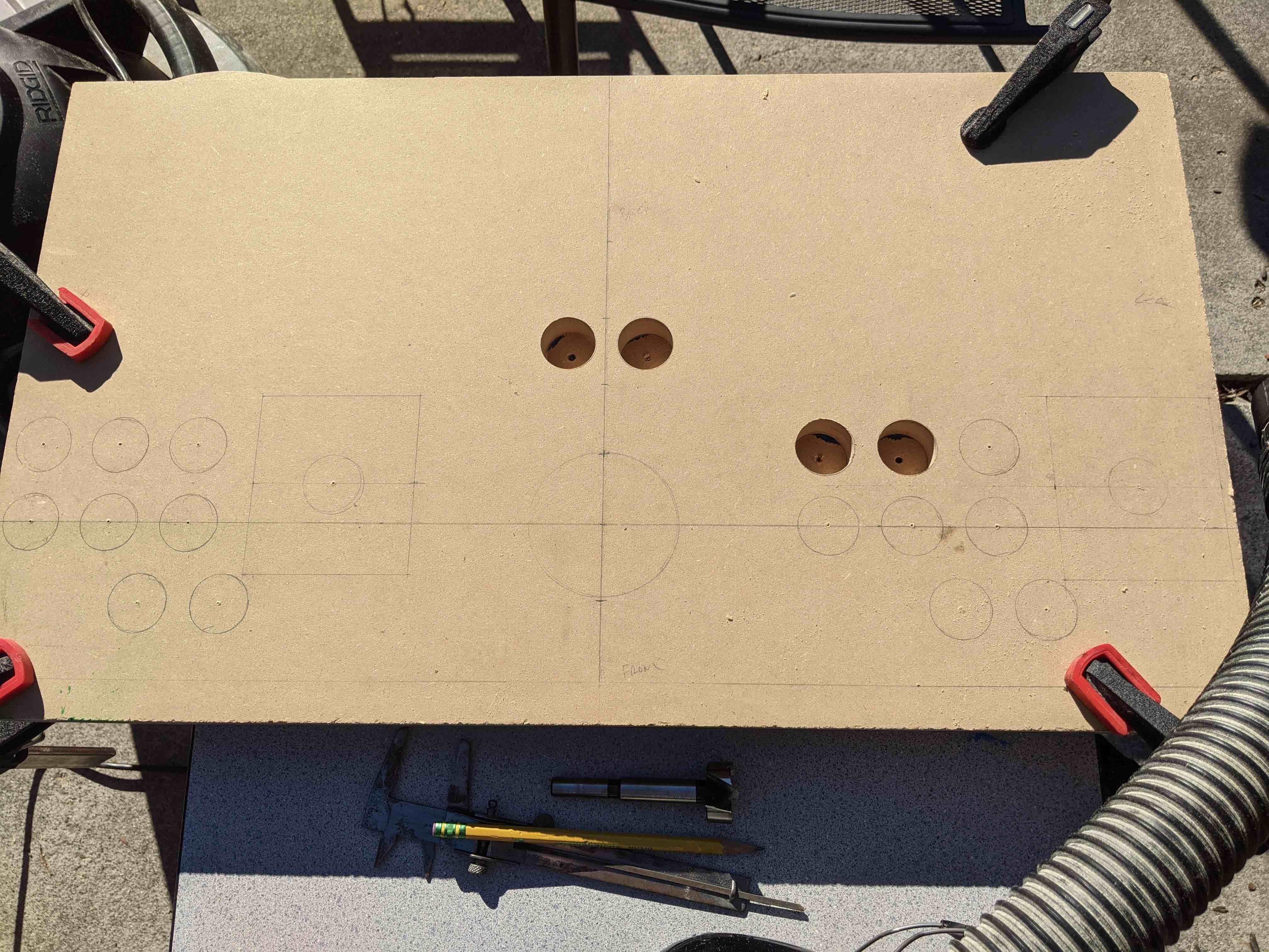
I forgot to take a picture right after sketching over the layout, but remembered to get one after drilling a couple of holes. The image shows the underside of the panel, so it's reversed. It's clamped to a layer of plastic and then a second MDF panel in the back to avoid blowout.
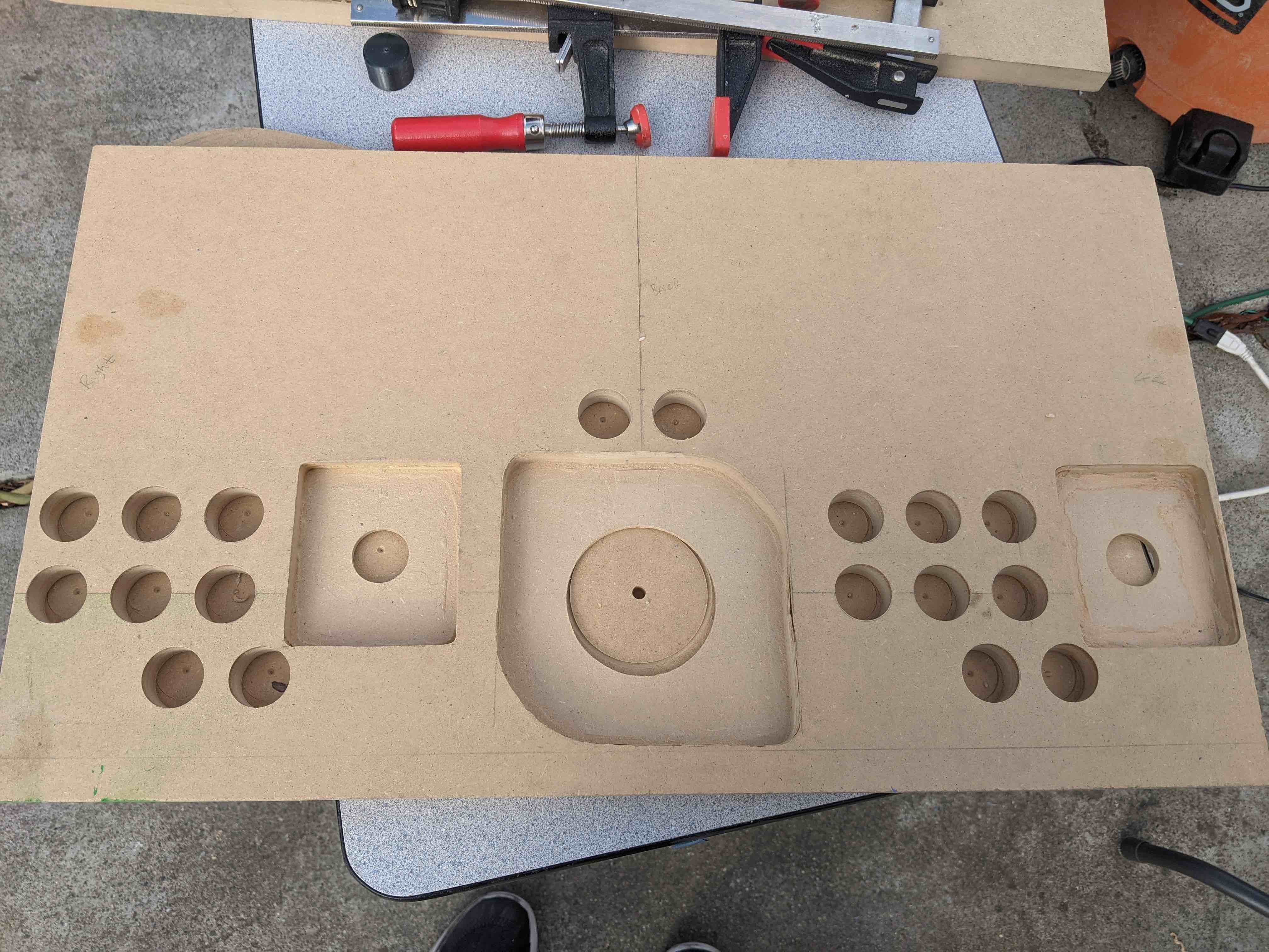
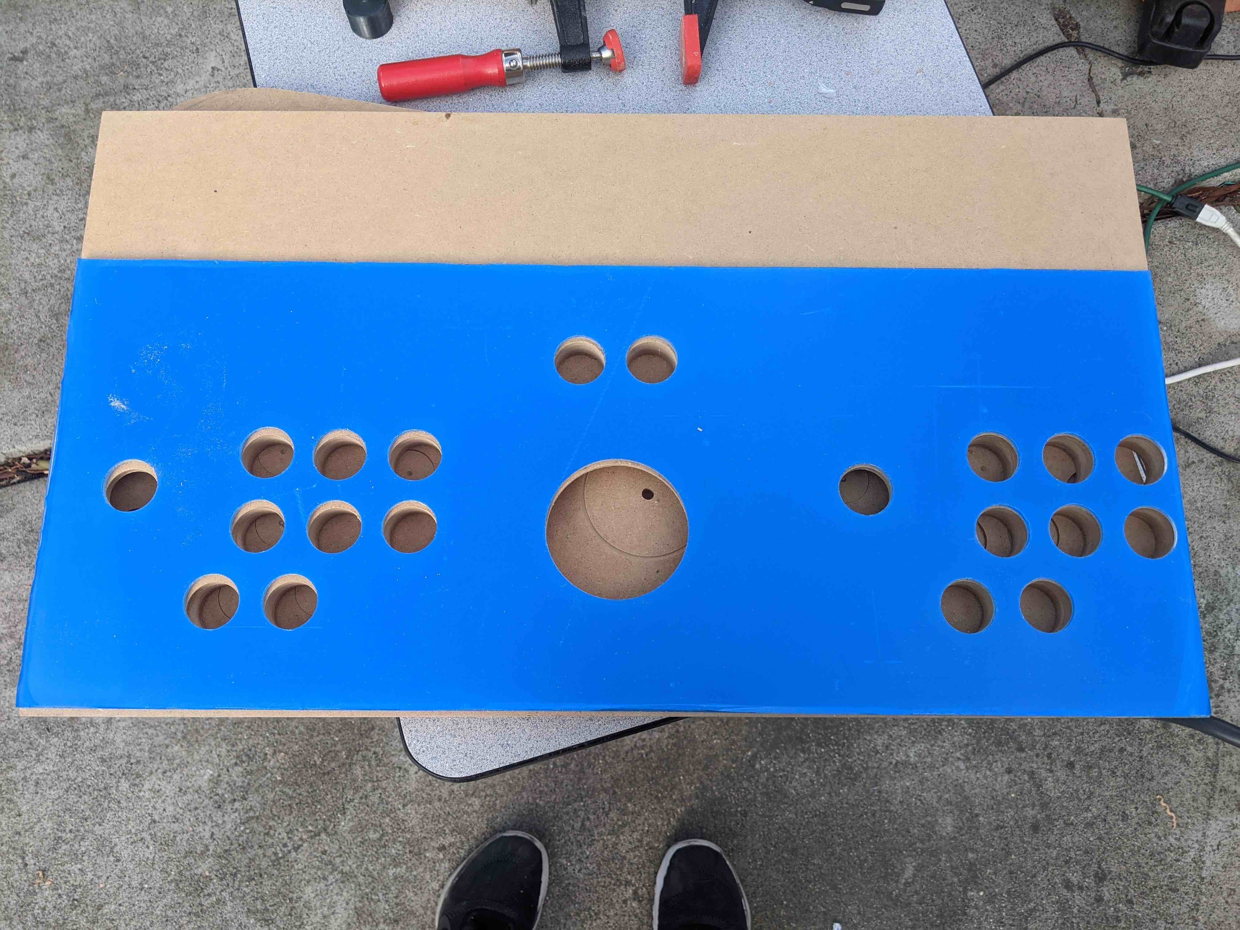
Below is the result. I routed a little bit too deep for the 1P joystick, so I had to add some wood filler. I was worried about cracks when drilling through the acryllic, but it turned out great! I used a forstner bit for the button holes and a hole saw for the large center hole. Don't mind the blue, it's just a protective film.
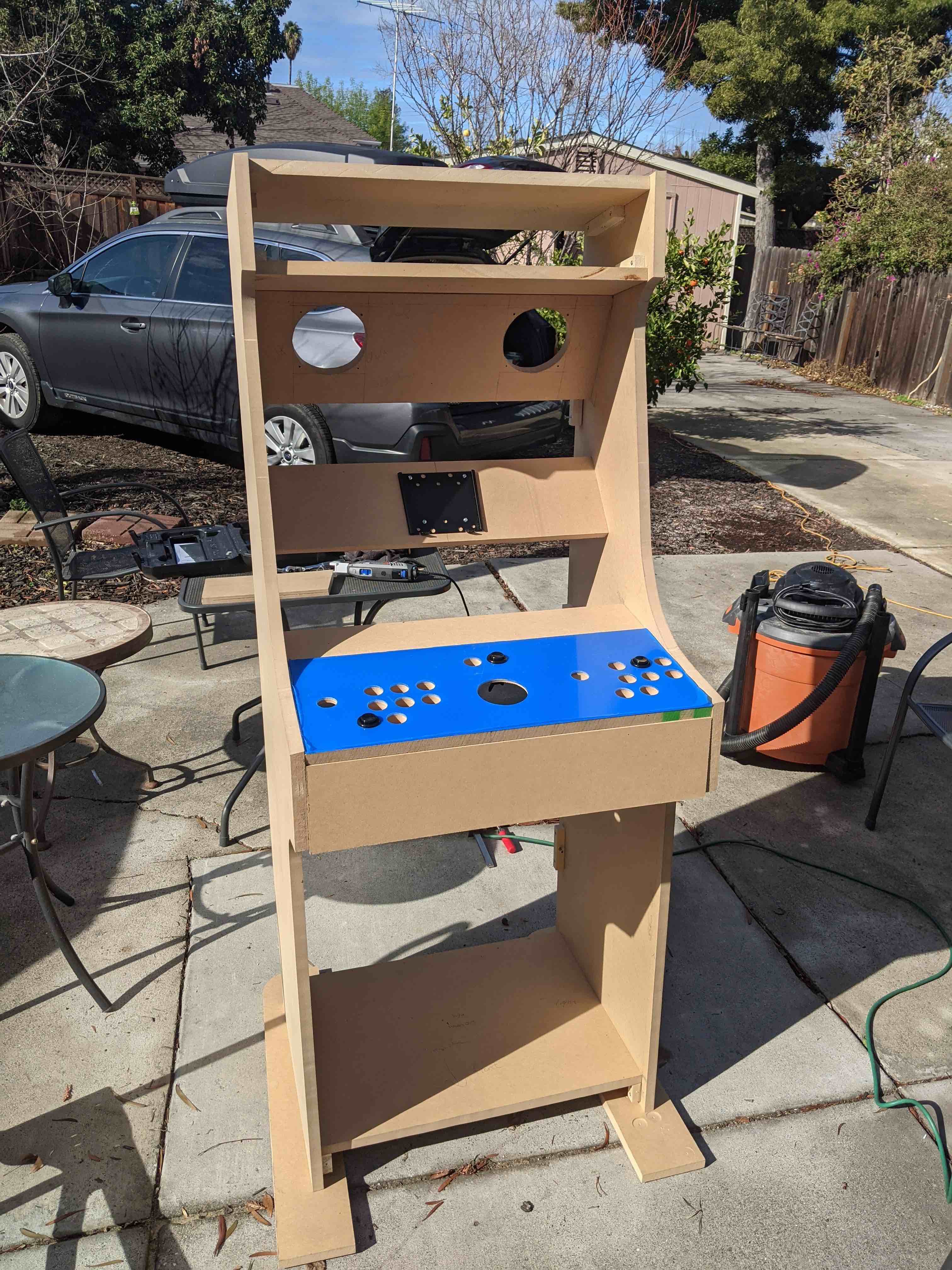
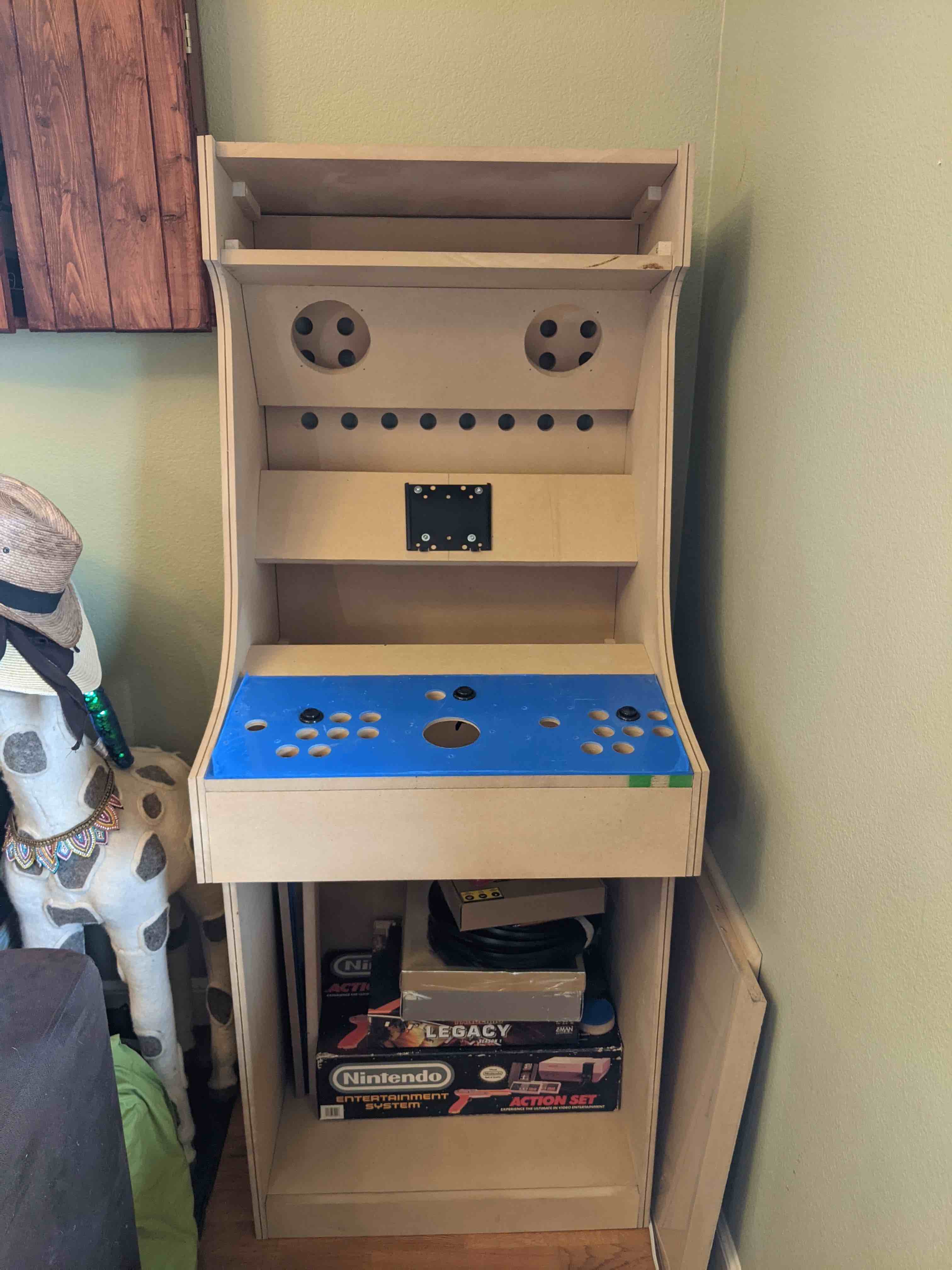
After this, I added the control panel and monitor mount to the dry fit cabinet. Everything fit pretty well! I had decided to add the acryllic to the control panel after I cut the panel that sits in front of the control panel so that piece was a bit long. You can see it extending past the side panels if you look closely in the picture. I ended up taking this piece out and trimming off a bit to clean up that edge.
With all the interior panels in place, there were just a few things left to do before I could start painting and putting it all together for the last time. I had to 1) route the edges for t-moulding; 2) cut holes in the back panel for the fan, the power plug, and ventilation; and 3) do a final sanding pass over the entire thing.
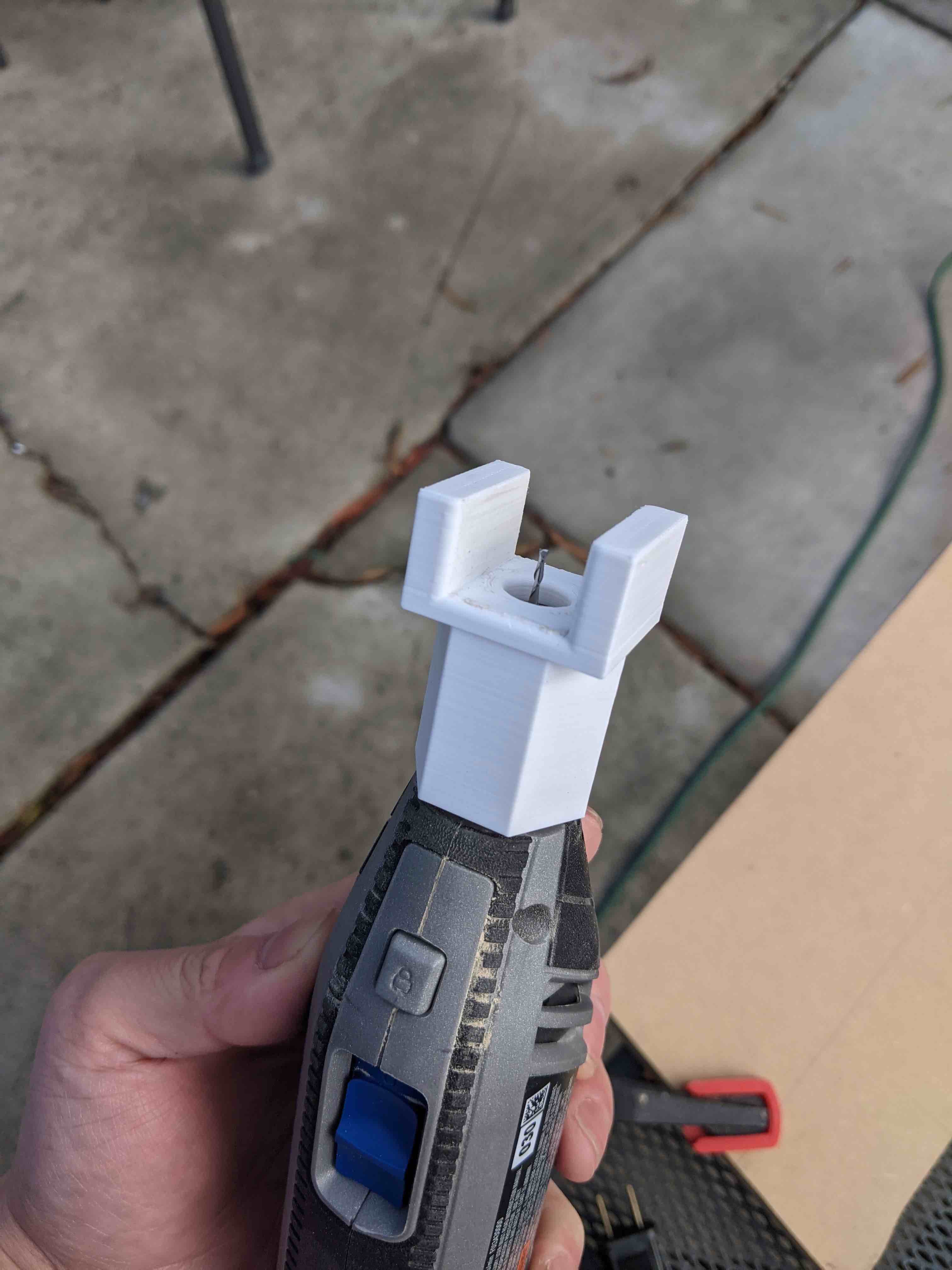
For the t-moulding, I needed to route a channel around the edges of both of the side panels. To do this, I modeled and printed a guide attachment for my dremel that I could use with a 1/8" router bit. The attachment screws onto the dremel attachment threads and is meant to keep the router bit centered on the edges of the panels. It also is the proper height to maintain the correct depth of the bit.
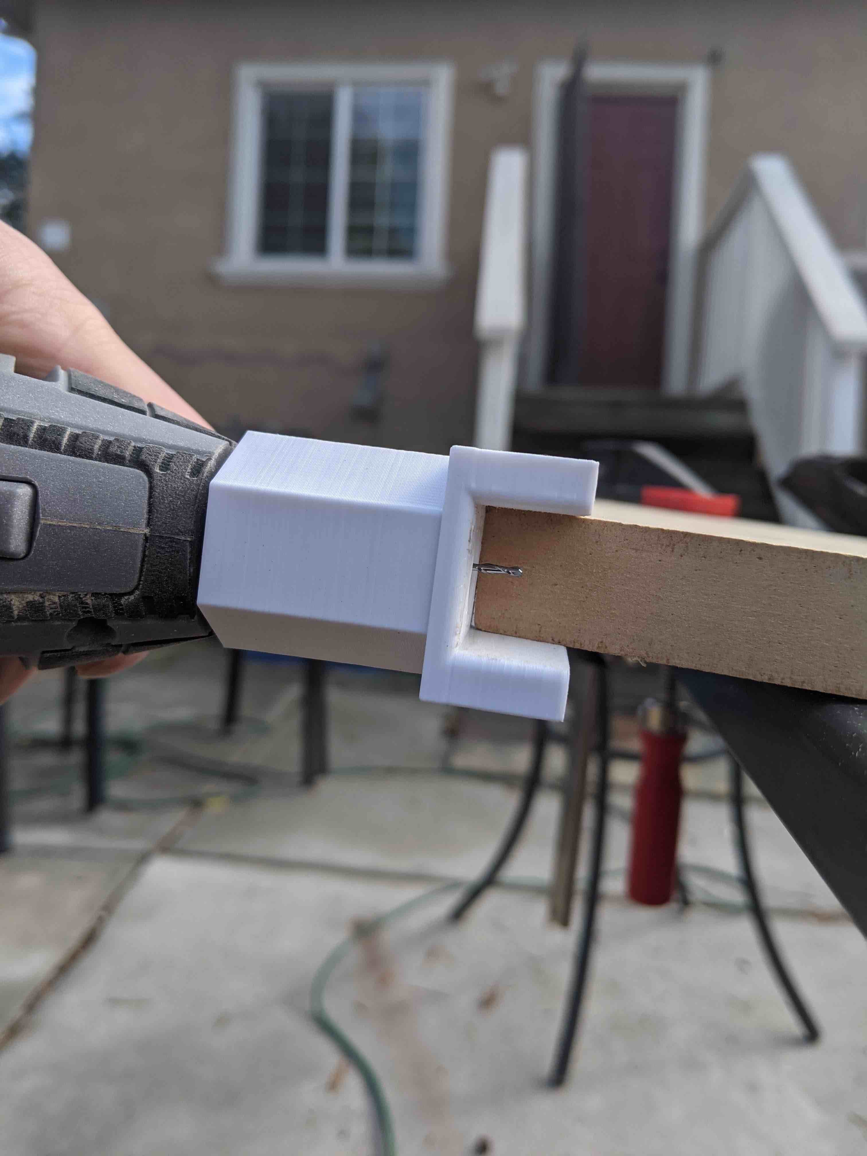
The attachment ended up working pretty well. The fit on the dremel was nice and snug, and the position of the drill bit was perfect. I found that the sawdust from the cut tended to get pushed into the base of the attachment, which I think added some stress to the bit since the new sawdust didn't have anywhere to go. At times, the stuck dust would also heat up and but a bit, which probably wasn't good. The next time I make an attachment, I'll definitely add some channels for dust to escape.
The holes for the back panel were all pretty straightforward. For the top ventilation, I drew out a grid of holes that I drilled out. I cut a hole for a cabinet fan on the bottom. The fan is meant to suck cold air in, which would in turn push warmer air out the top through the ventilation holes.
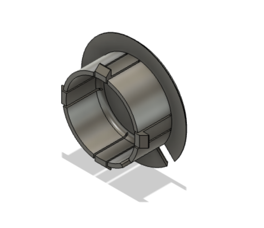
For the hole for the plug, I just drilled out a 2" hole towards the bottom that was big enough to feed any sort of plug through. I designed and printed a cap that cleans up the look quite a bit.
I didn't take pictures while preparing the back panel, but here's a picture of the final dry fit. You can see the t-moulding channels that have been routed down the edges of the side panels. The grid of ventilation holes can be seen towards the top and through the speaker holes. The fan and plug holes are blocked, but I promise they're back there.
After the final dry fit, I got to painting and putting things together. I painted without the back panel in place so it could be easily removed once it's all put together. Once painted, I was able to install the screen, speakers, and control panel and get that all wired together.
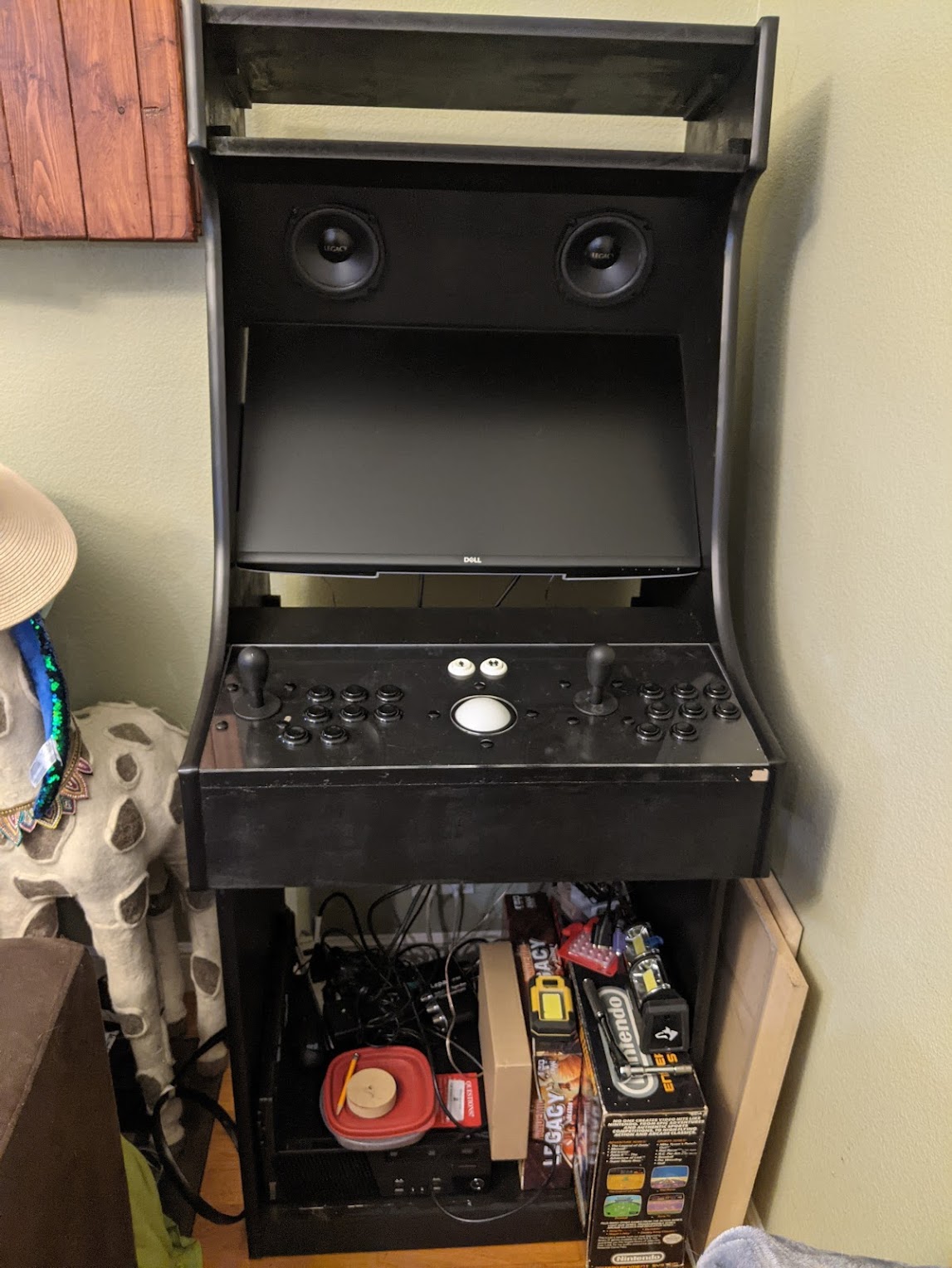
After throwing the computer in there, we finally have a functional arcade machine!
From here, it's just the finishing touches. I installed some lights behind the marquee, had some acryllic sheets cut, and printed out a Galaga marquee insert. These lights are plugged into a smart power strip that allows everything to be powered on once the computer is turned on.
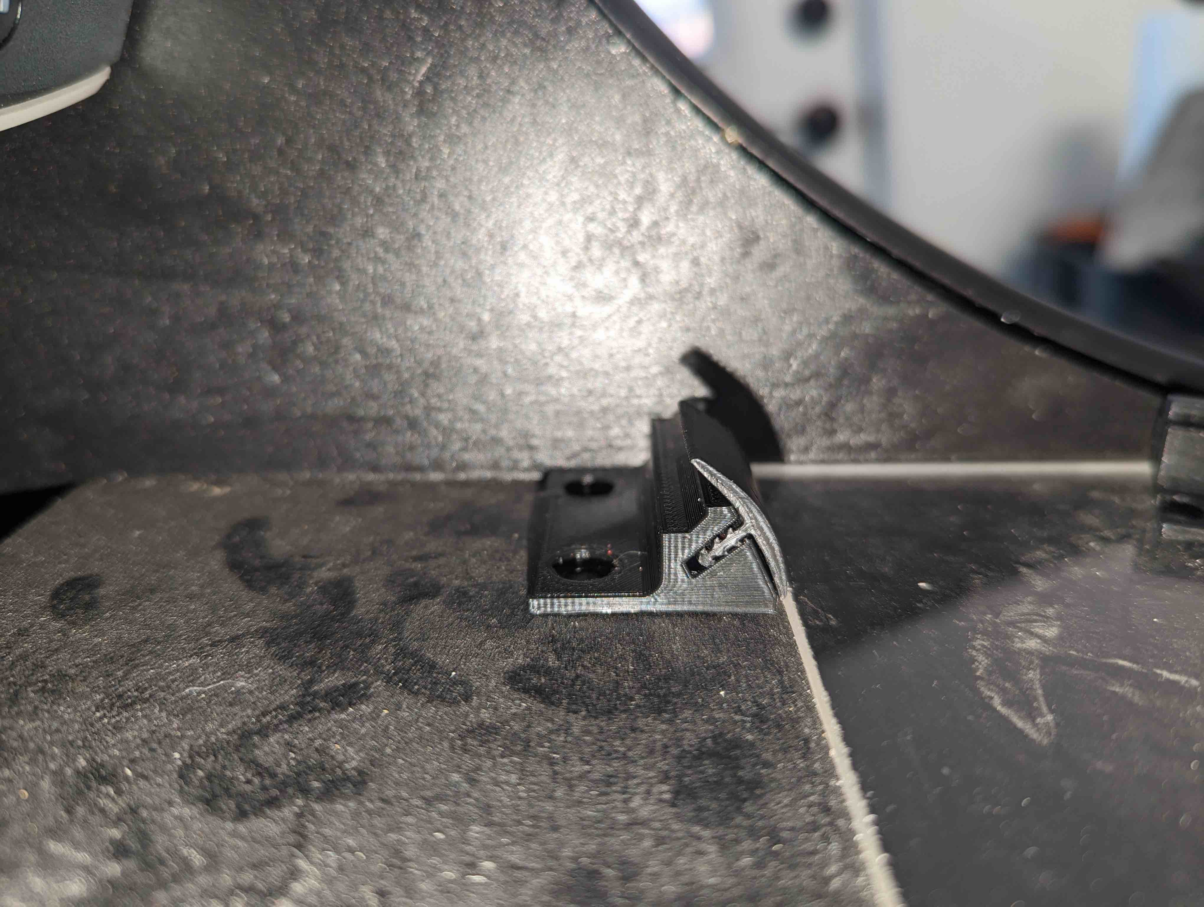
I had a piece of acryllic cut to be a screen in front of the monitor. I designed a little bracket to sit at the bottom of this sheet to raise it up a little bit and to mount some moulding to cover the seam. There's a slight difference in height needed between the left and right sides. The right side needs to be set back about 5mm more than the right side. One of the great things about 3d printing is that I can design different versions of brackets with the exact dimensions needed to make it seamless.
The build (and this page) is still in progress... come back later and there might be more here!
Go back to the MAME page!